The Blair Cuspids: The Second Photo
Since we published the web pages on Frame LO2-61H3, a photograph showing
some stratnge-looking shadows and the objects that cast them, we've learned
from Fran Ridge of Lunascan that NSSDC had informed him there was a second
photograph, LO2-62H3, that showed the "Cuspids" in Mare Tranquillitatus.
LO2-62H3 was taken 2.2 seconds after LO2-61H3, and the Cuspids moved to
oppposite edges of the camera's field of view in the time between the two
photographs. Other than that, there is little difference between the viewing
and lighting geometry of the photographs. The most obvious and interesting
difference between the photographs is the appearance of the largest of
the apparenly anomalous objects, referred to previously as Cuspid 5. Figure
1 below shows the object as it appears in the two photographs.
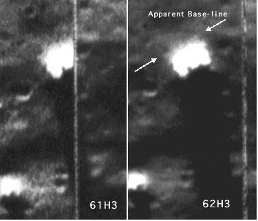 FIGURE 1
The image on the left is from 61H3, and the one on the right is from 62H3.
Both were scanned at the same resolution 2700DPI from the 8X10 inch negatives,
with one pixel equal to about 1/4 the quoted resolution for the Lunar Orbiter
camera at a 3:1 contrast ratio.
FIGURE 1
The image on the left is from 61H3, and the one on the right is from 62H3.
Both were scanned at the same resolution 2700DPI from the 8X10 inch negatives,
with one pixel equal to about 1/4 the quoted resolution for the Lunar Orbiter
camera at a 3:1 contrast ratio.
In Frame 61H3, part of the object is missing where it has been cut off
at a framelet boundary (misalignment of framelets was a problem with many
of the Lunar Orbiter images).
In Frame 62H3, it can be seen that there is a rounded lobe on the right
side of the object that matches the one on left, suggesting that the object
has a mirror-image symmetry. In 62H3's complete image of the object, the
boundary between its base and the lunar surface appears to be unusually
linear. This apparent base line is between the two white arrows pointing
toward each other in Figure 1. The apparent regularity of the objects'
base and mirror-image symmetry of its top would seem to be very surprising
features in a common lunar boulder.
The substantially greater width of the shadow near the Cuspid in 62H3
has little effect on the shape of the profile
of the object previously derived from compressing the shadow's image
from Frame 61H3 because the profile's width is influenced more by the width
of the shadow farther from the object, which is the full width of the object
in the first photograph and is not cut off by the framelet boundary. FIgure
2 shows the profile resulting compression of the Cuspid 5 shadow in Frame
61H3 after first moving the two adjacent framelts apart by the amount indicated
to be missing in 62H3. The slope illumination angle of 6.9 degrees used
to produce this profile is in the center of the range of angles previously
estimated from the apparent penumbra. As will be shown on the next page,
that angle is probably the best estimate of the illumination angle because
it is supported by photometric analysis.
 FIGURE
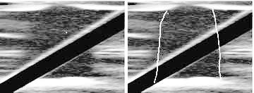
2 Profile of Cuspid 5 created from the shadow of the object from
LO2-61H3 taking into account the area missing due to framelet overlap for
a 6.9 degree sun elevation above the slope on which the shadow is cast.
The image on the right is the same as the one on the left, with the additions
of outlining to indicate the apparent edges of the object.
FIGURE
2 Profile of Cuspid 5 created from the shadow of the object from
LO2-61H3 taking into account the area missing due to framelet overlap for
a 6.9 degree sun elevation above the slope on which the shadow is cast.
The image on the right is the same as the one on the left, with the additions
of outlining to indicate the apparent edges of the object.
Due to some unavoidable blurring caused by the resizing algorithm used
to compress the shadow in Figure 2, it is difficult to see exactly where
the shadow boundary is. That might lead you to wonder whether I've been
a little too imaginative in how I drew the outline of the Cuspid on the
version to the right in Figure 2. However, you should be able to
satisfy yourself that the above profiles are reasonable given the sun angle
of 6.9 degrees by doing the fallowing:
-
Download this GIF
file (65K) of the 2700DPI close-up of the Cuspid 5 shadow with the
gap already inserted at the framelet boundary to compensate for missing
part of the image due to the overlapping framelets.
-
Measure the length of the shadow in the GIF. (You may have to adjust the
brightness and contrast to see the shadow's boundary clearly).
-
Measure the length, L, of the shadow from where it joins the object casting
it to its tip.
-
Measure the width, W, across the shadow perpendicular to its long axis
at various points.You may have to increase the contrast on this unenhanced
image and draw lines along the shadow boundary so that you can measure
across the part missing at the gap.
-
Multiply L/W (from Steps 3 and 4) by the tangent of 6.9 degrees (the sun
angle) to get the ratio of the object's height to its width at that point.
You should find that the height-ot-width ratio for the object, is approximately
1 near the base, but about half way above the base, the ratio is more like
1.25, or a height 25% greater than width.This object is no slender "spire",
but neither is it a shapeless boulder.Boulders tossed randomly seldom come
to rest in such an unstable position. The outlined image of Figure 2 should
be a good approximation of the object's profile as viewed from the lunar
surface looking toward the sun, assuming a sun angle of 6.9 degrees. As
I will discuss on the next and probably final Blair Cuspid page, photometric
analysis strongly suggests that this is more than a mere guesstimate.
Too Many "Cuspids"?
Figure 3 from Frame 62H3 shows a kilometer-wide crater a few hundred meters
to the north of the main group of objects. It can be seen that there are
quite a few objects casting sizable shadows in and around this crater.
Many of the shadows appear similar to those of some of the smaller Cuspids
that William Blair noticed were positioned at the apexes of isoceles and
equilateral triangles, an arrangement he thought suggested artificiality.
There is nothing to suggest that any of these other objects are anything
besides large rock fragments. There is certainly no indication of any pattern
to their positioning. Unless some criteria can be established that distinguishes
the debris strewn randomly around this crater from Cuspids of similar appearance,
the significance of the Cuspids' spatial arrangement appears doubtful.
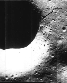 FIGURE 3
A one-Kilometer wide crater to the north of the Cuspids from LO2-62H3.
This image was scanned at 337 DPI from the negative. The main group of
Cuspids are a few hundred meters to the right of the position of this image.
FIGURE 3
A one-Kilometer wide crater to the north of the Cuspids from LO2-62H3.
This image was scanned at 337 DPI from the negative. The main group of
Cuspids are a few hundred meters to the right of the position of this image.
A Baby Tooth?
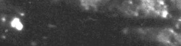
The arrow in Figure 3 points to a shadow of a different shape from those
of the others around this crater. The object casting this shadow is perched
on the eastern edge of the crater. As shown in Figure 4 below, the shadow
is needle-like, suggesting that the object casting it could be similar
in shape to the largest of the Cuspids, #5, although this object is much
smaller.
FIGURE 4 "Cuspid 6," the Crater Cuspid. Object
and shadow on the eastern rim of the crater of Figure 3.The image was scanned
from LO2-62H3 at 2700 DPI. This shadow and the part of the crater it is
near were not visible in LO2-61H3 because they were off the edge of the
photograph. The image has been rotated 90 degrees counter clockwise here
from its orientation in Figure 3 so that the entire shadow fits on the
monitor. Note the bright object at far left of the image, which is casting
the shadow.
The shadow is obviously being cast downslope into the crater, which
might lead the astute observer to suspect that the shadow's length has
been greatly exaggerated by the slope in the way previously
explained. However, the slope is much less along the crater rim in
the direction the shadow points than it would be if the shadow were pointing
toward the crater's center, where it is deepest. This couuld mean that
the object casting the shadow might still have a significant height.
But this "maybe" and "might be" sort of argument will never lead to
a reasonable estimate of what the shape of the object actually is. The
shadow is too small to detect any indication of a penumbra, which was
previously
used for a rough estimate for the height of Cuspid 5. We have learned,
however, that the Lunar Orbiter negatives do contain sufficient photometric
information for estimates of the terrain slopes. A preliminary analysis
not only suggests that "Cuspid 6" does have an anomalous morphology, but
the same technique supports the estimate previously made for the shape
of Cuspid 5. An image displaying the probable profile of this new object
will be shown on the
next page, but first you'll have to wade through some discussion of
basic photometric principles before you get to it.
Cuspids Page
5: Photometric Analysis of the Slopes
Cuspids 3
Cuspid Page
2
Cuspid Pag
1
Back to VGL Home Page